Loco No.1
Loco No.1 is based on the one used on the Hellingly Hospital Railway, which connected the East Sussex County Asylum with the mainline, and was used to carry coal deliveries to the hospital’s boilers. Though it was standard gauge, the loco’s narrow body on very wide frames give me the impression that it was based on an off-the-shelf European narrow gauge design, modified to serve as a small standard gauge loco. My model depicts the hypothetical narrow gauge version.
![]()
Picture from Wikipedia, copyright expired.
The Hellingly Hospital loco. Note the difference in width between body and frames.
Construction
Power for the loco is provided by a Black Beetle motor bogie. It was all that survived my first attempt at building the loco, which became badly warped and had to be scrapped.

Drawings of the loco are included in Peter Harding’s book The Hellingly Hospital Railway, which I have used as the basis for the model. I assembled the basic shell from styrene sheet. To make sure I got the curved bonnet sides exactly correct, I stuck copies of the drawings to the styrene with Pritt Stick, cut along the outlines, then peeled the paper off. The only change I have made to the body to make it suitable for narrow gauge is to give it flush sides, rather than wide frames. Otherwise it is an accurate 1:43 model of the real thing.

The rims around the cab windows were added by curving microstrip around a styrene former, which fitted through the window from the inside. This enabled me to achieve a much neater shape than I could manage freehand.


On the underside I added plenty of longitudinal reinforcement to minimise the chances of warping occurring again. The slot through the floor is to allow for a DCC decoder in the cab to be connected to the Black Beetle motor bogie, should I wish to add one in the future.

To form the basic shape of the roof I used layers of styrene, on a removable base to permit access to the cab for painting and detailing.

Squadron filler was then applied to fill in the “steps”…

…and sanded smooth once dry.

Thin styrene was glued over the filler to give the roof a smooth and strong surface. Microstrip was used to add the rainstrip.

The chassis is attached to the body using a screw at either end, one on each side of the loco. These pass through a nut glued above the floor of the loco body, and further secured with some milliput filler.

I built a plastic box around the nut and screw to protect it from the lead weight which I put in the bonnet to improve traction.


To represent the strengthening around the cab door opening, I first covered the whole area in a layer of styrene, then cut away the inside area and filed it smooth.

A narrow styrene strip was then glued around the inside of the opening to form the other part of the reinforcement.

To make the curved front of the bonnets, I used 0.3mm styrene, which I first glued on to the sloping part of the bonnet to get it strongly fixed.

The curved front glued on and filed flush at the sides, and with the central raised strip made from another layer of styrene.

I made some interior details, based on tramcar controls, from odd bits of styrene and wire. I’ve no idea if they are correct, having never seen a photo of the inside of the Hellingly loco’s cab, but they look OK.

I also added handrails, made from some brass wire, and “knobs” on their ends from a bit of milliput.

The Hellingly loco had over 700 rivets on it, I number which surprised me somewhat once I’d finished counting them. On the model I’ve used Grandt line plastic rivets, which have to be fitted into holes drilled in the body. To position them accurately I pritt-sticked copies of the drawings over the body so I could drill through the rivet locations shown on the drawing. This photo also shows a test fit of the Sommerfeldt bow collector.

A sprue of Grandt Line rivets. I needed over 20 of these.

With the drawings peeled off and the holes drilled the loco looked a right mess…

…but once all the rivets were added and the loco cleaned up it looked a lot neater.

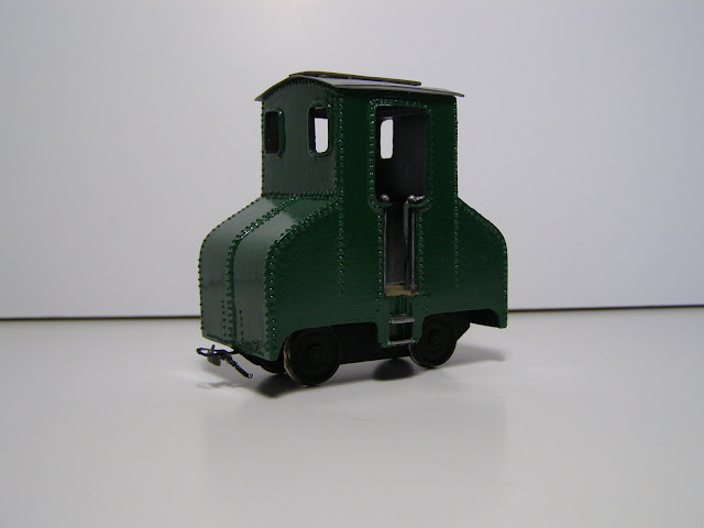
After a spray of white primer, I have brushed on about six coats of green paint. The colour I wanted was only available in gloss, but a coat of matt varnish will sort out the unrealistic shine.
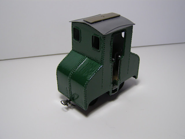
That’s progress so far, I have a bit of weathering to do to finish the loco off. To finish for this description, here’s a video of the loco being tested on 18cm radius curves, just to see how tight a corner it would go around without derailing.
