Track
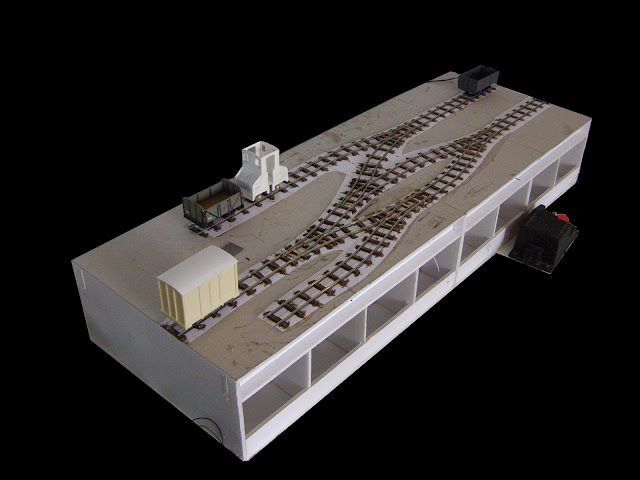
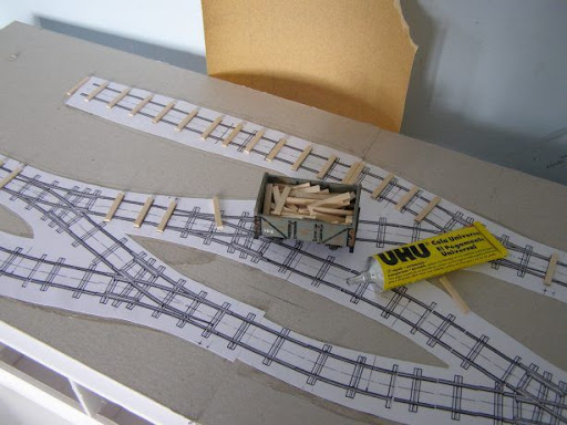
Track laying started by sticking a print out of the track plan using KBscale templates to the surface of the board. This allowed me to accurately build the track in-situ.
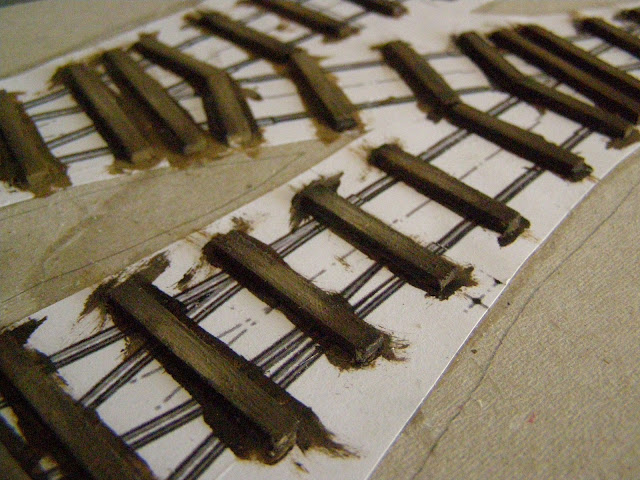
For the sleepers I used strips of limewood from my local model shop, which I cut to length and glued over the plans.
Once the sleepers were in place I used coarse sandpaper to give them a woodgrain effect, before painting them using various shades of brown enamel paint.
While making the track I have worked from photos of the Sitttingbourne and Kemsley Light Railway, which inspired my interest in narrow gauge. I took the photos at their gala in September 2008, which at the time looked like it would be their last open day before dismantlement.
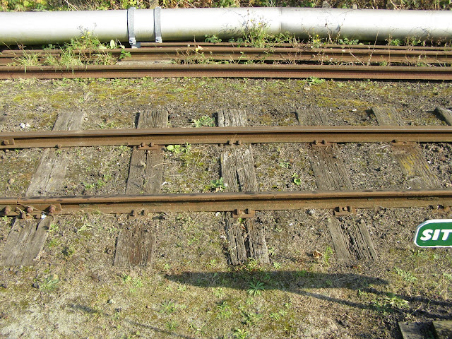
I really like the rotten, mossy, overgrown appearance of the SKLR’s track, though the volunteers running it may not share my views.
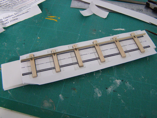
The process of adding the rails is best illustrated by the small test track I experimented with. First one of the rails was superglued then pinned in place – I used needle nose pliers to drive the pins through the sleepers.
Then I used 16.5mm roller gauges to locate the second rail, and tack it with superglue.
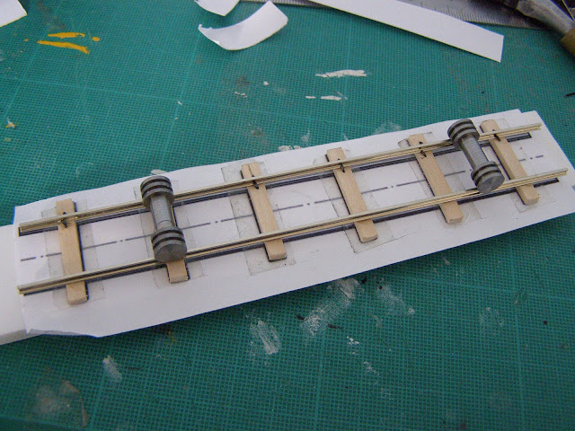
I could then pin it down firmly to hold it secure.
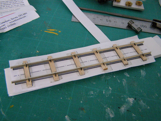
The rail was Peco code 81, and the pins are from KBscale.
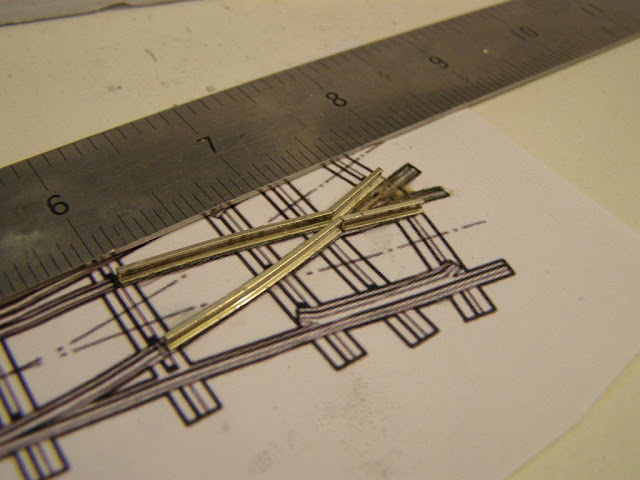
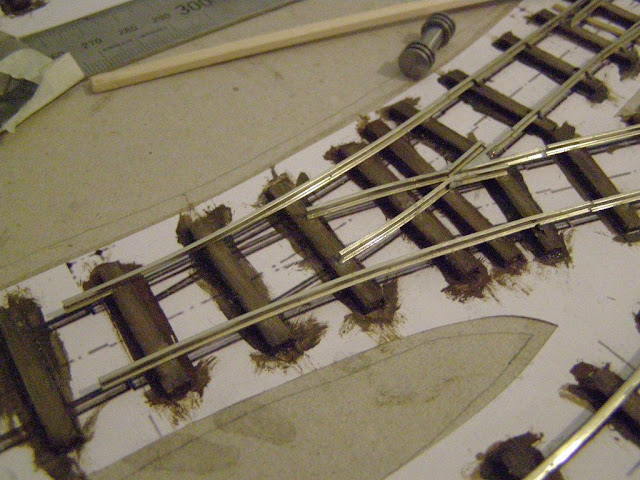
For points, I curved the rail to the correct radius using the KBscale rail bender. It has settings for large and small radius O-14 left or right handed points, but these are not quite right for Y points, especially when made to 16.5mm gauge. Therefore I had to continue the bending process by hand to achieve the desired radius.
Similarly, the KBscale crossing jigs should work for 16.5mm gauge left and right handed points, but are not suitable for Y points. Instead I had to superglue the rails to copies of the track templates and solder them together there, then remove the paper before filing everything smooth and fixing the rails to the sleepers.
As electrofrog points, a SPDT switch was needed to control the polarity of the frog. I also needed something to act as an over-centre spring to keep the blades firmly to one side or the other, so I decided to combine the two functions.
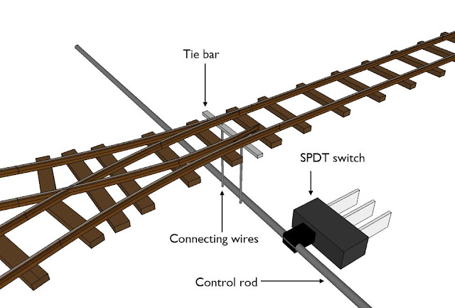
The two vertical brass wires attached to the blades pass through the board and are attached to the horizontal control rod. I wanted to solder them, but whatever metal the control rod is made from seems to be completely impervious to solder. Instead I first glued the wires to the rod, then moulded Milliput filler over the joint to strengthen it.
The control rod runs through holes in the front and rear of the board, which hold it in place, and through the lever of a SPDT slide switch. The switch controls the polarity of the point, and provides the over-centre spring to hold the blades in place on the right or left.
Once all the rails were fixed down, I painted the sides of them to represent the rust and grime of many years exposure.
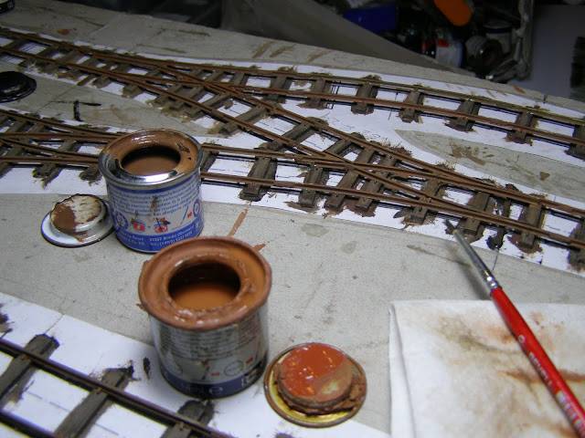
The colours I used were Humbrol 62 and 29, with some 6, as well as Revell 37, 83, and some 85 – if it’s brown and comes in a small expensive tin, I probably used some.
Progress on the board has pretty much stopped with all the trackwork done, as since then I’ve been working on the buildings before I move onto ballasting.